Reference Guide: MTP/MPO Cabling for 400G Networks
Introduced in late 2018 and early 2019, the 400G switch entered the market and many expected that 400G would see real adoption in 2020. In fact, the data center market analyst Dell'Oro predicts that the shipments of 400G switch ports will reach 15 million by 2023. Keeping pace with this trend, many suppliers are committed to offering various 400G transceivers and MTP/MPO cabling solutions to meet the high-performance 400G network. This article will introduce 400G MTP/MPO cabling and present some of the application scenarios.
A Glance at 400G Optics and MTP Cables
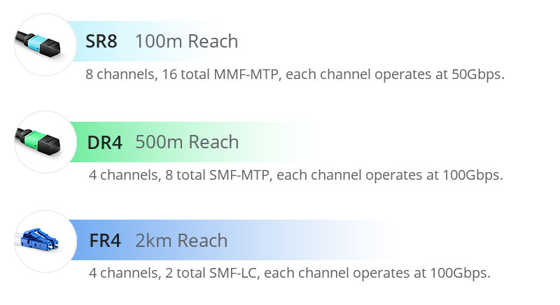
With the emergence of 400GbE, 400G optical transceivers with multiple types are springing up such as 400G-SR8, 400G-DR4, 400G-FR4, 400G-FR8, 400G-LR8, and 400G-SR16, etc. Among them, 400G-SR8, 400G-DR4 and 400G-FR4 transceivers in both the QSFP-DD and the OSFP form factors have been widely demonstrated publicly and are already sold by optical transceiver vendors in the market.
Standardized by the IEEE P802.3cm Task Force, 400G-SR8 QSFP-DD/OSFP transceivers are designed to provide cost-effective short-range transmission by adopting 16-fiber parallel multimode MTP cables. In accordance with the protocol IEEE 802.3bs Task Force, 400G-DR4 QSFP-DD/OSFP transceivers adopt 8-fiber or 12-fiber parallel single mode MTP cables, which can achieve 500m reach. Unlike the previous two, the 400G-FR4 interface only utilizes 4 lasers instead of 8 lasers to multiplex them into one fiber in each direction. 400G-FR4 QSFP-DD/OSFP modules are normalized by the 100GLambda MSA to provide long-range transmission with 2-fiber single mode LC cables.
Consequently, MTP cabling is mainly used together with 400G-DR4 and 400G-SR8 optical transceivers in 400G networks, which can be further divided into 8-fiber, 12-fiber, 16-fiber SMF and MMF MTP cables types.

Figure 1: SR8-vs-DR4-vs-DR8
MTP Cabling Solution for Typical 400G Network Application Scenarios
In 400G data centers, there are mainly four cabling scenarios: 400G-400G, 400G-4x100G, 400G-2x200G, and 400G-5x80G. Combining the above mentioned 400G modules with matched patch cords, a flawless direct connection or interconnection will be realized. In this section, it will focus on the direct connection MTP cabling solutions for the four scenarios.
400G-400G Direct Connection
400G-DR4 OSFP/QSFP-DD to 400G-DR4 OSFP/QSFP-DD
The term "DR4"—"DR" stands for 500m reach using single mode fiber and "4" implies there are 4 x 100 Gbps optical channels. Since one optical channel requires two fibers, an 8-fiber or a 12-fiber MTP cable can be used for the 400G-DR4 module to achieve direct connection. In the 8-fiber MTP cabling, the fiber utilization is 100%, while in the 12-fiber MTP cabling, four fibers remain unused. Take 400G QSFP-DD module as an example, the following picture is presenting the MTP cabling for 400G DR4 direct connection.

Figure 2: 400G-400G Direct Connection Scenario 1
400G-SR8 OSFP/QSFP-DD to 400G-SR8 OSFP/QSFP-DD
The term "SR8"—"SR" represents 100m reach adopting multimode fibers and "8" implies there exist 8 optical channels with each operating at 50Gbps. Normally speaking, 400G-SR8 modules use 16-fiber MTP cables with 100% fiber utilization for direct connection. These 400G-SR8 fiber optic transceivers' primary adopters are expected to be certain hyper-scale cloud service providers in North America and China.

Figure 3: 400G-400G Direct Connection Scenario 2
400G-2x200G Direct Connection
400G-SR8 OFSP/QSFP-DD to 2x200G-SR4 QSFP
In the backbone and some more complex metropolitan area networks, the dual-carrier technology (2x200G) will be adopted to compress the channel spacing compared to a single-carrier 400G technology. Extending the transmission distance and improving the spectral efficiency, 400G-2x200G direct connection can help to deploy 400G backbone networks with minimum bandwidth resources.
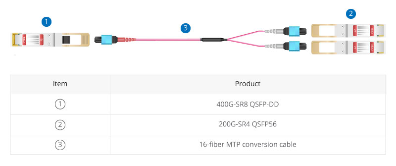
In this case, MTP conversion cables terminated with MTP connectors on both ends are needed. With this type of cable, one 400G OFSP/QSFP-DD module and two 200G QSFP56 modules can be directly connected.

Figure 4: 400G-2x200G Direct Connection Scenario
400G-4x100G Direct Connection
400G-DR4 OSFP/QSFP-DD to 4x100G-DR QSFP
The architecture of 400G-4x100G employs 4 wavelengths at 100Gbps. However, the current 100G technology is based on 4x25G design and unable to scale to 400G. PAM4 technology is adopted to achieve 100Gbps per channel, and then achieve overall 400Gbps speed by 4x100G aggregation. The MTP cables allow splitting of 400G bandwidth into multiple 100G or 40G data streams.
In the scenario of 400G to 4x100G migration, the following components can't be ignored: An 8-fiber MTP-LC cassette that packaged in the fiber rack mount enclosure is adopted to realize the transmission from MTP to LC. One 8 fibers MTP/MPO trunk cable and four LC duplex patch cables are connected on either end.

Figure 5: 400G-4x100G Direct Connection Scenario
400G-8x50G Direct Connection
400G-SR8 OFSP/QSFP-DD to 8x50G-SR SFP
The rapid development of 400G has promoted the less popular 50G market to a certain extent because 50GbE also provides the technology to scale for the coming 400G (8x50G) network. Eight 50G lanes can support the optical link of 40Gbps aggregation via PAN modulation.
For this scenario example, the MTP cassette is in the middle to connect the 16-fiber MTP conversion cable and the LC duplex patch cords together to realize the 400G-8x50G direct connection.

Figure 6: 400G-8x50G Direct Connection Scenario
Scaling to MTP Cabling System for 400G Networks
400G is increasingly becoming ubiquitous in many high-performance and high-density networking environments. With the popularization of 400G networks, MTP cabling has been widely used in data centers as a prevailing cabling solution. FS, staying ahead of the curve, has provided a wide range of relevant 400G MTP products to realize a smooth 400GbE connection or the migration of 400G-4x100G, 400G-2x200G, and 400G-5x80G.
Related Articles
MTP® vs MPO Cable: What Are the Differences?
Migelle March 9, 2020 There comes a more demanding request for higher transmission speed and larger capacity with the prevalence of cloud computing in the era of big data. 40/100G networks are increasingly becoming more commonplace in data centers. ...A Comprehensive Guide to MTP® Connector
Howard July 21, 2020 MTP® connector is a component widely applied in high-density network applications such as most data centers, broadcast communications, and industrial control applications, and MTP® cabling has been welcomed by a large number of ...PoE Cabling Explained: Architectures, Advantages, and Applications
Worton June 23, 2020 Power over Ethernet (PoE), no longer a new buzzword, is shaping the current network ecosystem. Be it digital transformation, Internet of Things (IoT), NextGen wireless, smart devices solutions, etc. are all in rapid growth with ...Quick Guide to Power Distribution Unit (PDU)
Worton May 16, 2020 Power distribution unit, also known as PDU, refers to a device fitted with multiple outputs designed to control and distribute electric power, which is normally used in the racks of networking equipment located in a data center. A ...Patch Cable vs. Crossover Cable: What Is the Difference?
Stephane December 27, 2020 Despite advances in wireless technologies, many computer networks still rely on cables as a physical medium for devices to transfer data. Several standard types of network cable exist, including coaxial cable, twisted pair ...
